")
What a Skived Fin Heat Sink Is
Definition and Process
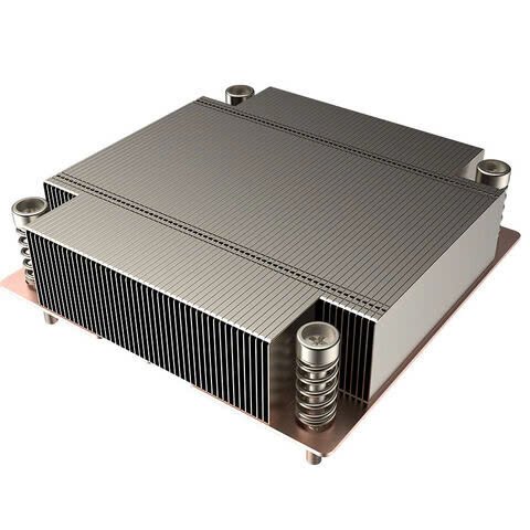
A skived fin heat sink is manufactured by slicing thin layers of metal from a solid billet (typically aluminium or copper), and bending those slices upright so they form fins that remain integral with the base. The process is described by CTX Thermal Solutions: “In the skived fin process the heat sink is pared out of an aluminium or copper block. This produces heat sinks with high density on very fine fins which are directly connected to the heat sink base.”
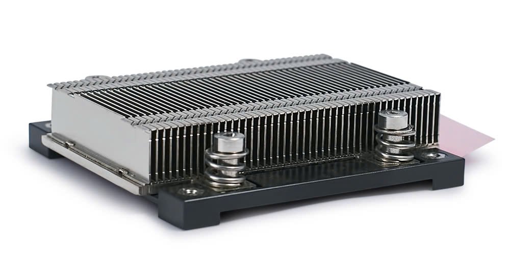
Because the fins and the base share the same material and there is no solder, brazing or bonding interface, thermal resistance from base to fin is minimized. Wikipedia notes: “A PC-cooler created by skiving has the benefit that the heat sink base and fins are created from a single piece of material (copper or aluminium) … the fins may be made much thinner and closer together than by extrusion.” Wikipedia
Why this matters
In thermal design, interface resistance and fin density commonly limit what you can achieve. A skived fin heatsink bypasses those typical boundaries: you get more area in the same volume, and the conduction path from source to fin is shorter. That matters especially in high-power, compact systems where space and thermal budgets are tight.
Key parameters to track: fin thickness, fin spacing (pitch), fin height, base thickness, material choice.
Skived Fin vs Other Fin Heat Sink Types
Skived vs Extruded
-
- Extruded fin heat sink: material is forced through a die to form fins. Lower tooling cost for large batches; fin geometry limited by extrusion die and metal flow.
-
- Skived fin heat sink: much tighter fin spacing possible (even < 0.3 mm in some designs) thanks to the slicing method. EKL-AG reports fin spacing of < 0.3 mm possible with skiving. ekl-ag.de
-
- Interface: skived has no fin-to-base interface; extruded is one piece too but fin geometry is more limited.
Skived vs Zipper / Stacked Fin
-
- Stacked fin heat sink: fins are stacked (often punched) and attached to a base; interfaces exist (fastener, brazing, adhesive).
-
- Zipper fin heat sink: fins are formed and assembled like “zipper” structures.
Both can achieve high density but the multiple interfaces increase resistance and may complicate reliability. Skived keeps fins integral, for faster conduction and simpler mechanical path.
- Zipper fin heat sink: fins are formed and assembled like “zipper” structures.
Summary Table
| Type | Fin Density | Interface | Typical Cost Situation |
|---|---|---|---|
| Extruded fin heat sink | Moderate | One-piece | High volume, moderate cost |
| Stacked/zipper fin heat sink | High | Multiple joints | Mid-volume, moderate cost |
| Skived fin heat sink | Very high | No fin-base interface | Low-mid volume, premium value |
>>Read more: Skived Fin Heatsink: Superior Cooling with Seamless Efficiency
Materials and Surface Finishes
Aluminium vs Copper
Aluminium (e.g. 6063 alloy)
-
- Pros: lightweight, lower cost, good conductivity (~200 W/m·K) compared with copper (~390 W/m·K) in many alloys.
-
- Use when mass sensitivity or cost is key, and airflow or geometry allows.
Copper (C11000 or similar)
- Use when mass sensitivity or cost is key, and airflow or geometry allows.
-
- Pros: higher thermal conductivity; supports narrower fins and tighter spacing for the same thermal load.
-
- Cons: heavier, more expensive material; may require plating (e.g., electroless nickel) for corrosion control or solderability.
EKL-AG explains that skived fin radiators are “manufactured from pure copper or thermally highly conductive aluminium alloy.” ekl-ag.de
- Cons: heavier, more expensive material; may require plating (e.g., electroless nickel) for corrosion control or solderability.
Surface Finishes and Coatings
-
- Anodizing (Aluminium): increases corrosion resistance, can improve emissivity; typical thickness and color control matter.
-
- ENP (Electroless Nickel Plating) (Copper): provides stable surface, reduces oxidation, aids solderability or assembly.
-
- Black Oxide / Powder Coat: less common for high thermal performance but used when aesthetics or environment dictate.
Key Design Levers for Performance
Fin Thickness, Spacing and Height
-
- Fin thickness (t_f): thinner fins allow more fins per unit width and thus more surface area. But thin fins may be mechanically fragile and may hinder airflow if spacing is too tight.
-
- Fin spacing (pitch): tighter spacing → higher fin count → more area. But also higher airflow resistance (ΔP). EKL-AG references fin spacing < 0.3 mm in some skived designs. ekl-ag.de
-
- Fin height (h_f): taller fins increase area, but their benefit depends on whether the airflow can penetrate the depth; also height increases mechanical risk and possibly thermal spread limitations.
Base Thickness and Heat Spreading
A thin base may not spread heat well from a concentrated source; leads to higher temperature gradients at the base → less efficient fin usage. Wikipedia: on heat sink design, spreading resistance is significant when heat travels from a small area to a larger fin field. Wikipedia
To minimize spreading resistance:
-
- increase base thickness if die area is small but heat flux high
-
- use a higher conductivity base (e.g., copper)
-
- consider integration of a vapor chamber if the spreading area is large
Airflow and Pressure Drop
For a fin heat sink, the performance is as much about airflow as fin geometry. In skived fin designs where fin density is high, you must ensure adequate air velocity so the fins are effectively cooled. EKL-AG states: “In combination with other cooling technologies … the cooling performance can be significantly increased.” ekl-ag.de
Key link: Fin density ↔ surface area ↑ but airflow resistance ↑ → fan or blower capability must be validated.
Material & Thermal Path
Because skived fins are integral with the base, the conduction path is simplified. That improves thermal conductivity from base to fin. It’s important to ensure the base interface (TIM, plating, flatness) is optimized because the skived fin structure only saves you so much if the base-to-device interface is weak.
Typical Specifications and Manufacturing Capabilities
-
- Fin thickness: some aluminium skived designs can go as low as ~0.25 mm; copper skived possibly ~0.1 mm in niche cases. EKL-AG mentions < 0.3 mm fin spacing. ekl-ag.de
-
- Fin height: large skived sinks may reach fin heights upward of 100 mm in some copper applications; smaller board-level solutions often stay under ~50 mm for mechanical robustness.
-
- Fin spacing: extremely tight in some designs thanks to the skiving process (e.g., ~0.1-0.3 mm).
-
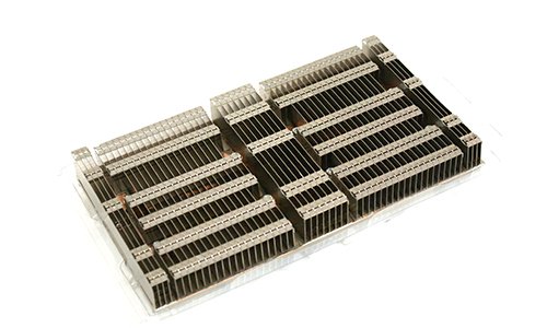
- Production volumes: Skived fin heat sinks can be cost-effective in low to medium volumes because tooling costs are lower than extrusion dies. CTX states “Low tool costs and therefore also suitable for small series” in its description. ctx.eu
-
- Material blocks: using solid blocks means you have freedom of geometry but cost of material and machining time must be considered.
-
- Finish options: Standard anodize for Al, ENP for Cu, optional powder or paint if environmental/aesthetic.
Applications Where Skived Fin Heat Sinks Make Sense
-
- High power density electronics (Nov 2025): Servers, GPUs, accelerators where footprint is small and heat flux is high. The ability to pack thin fins gives a real thermal advantage.
-
- Compact embedded systems: When height is limited but airflow exists (e.g., blower forced flow), skived fin designs outperform typical extruded fin heat sink alternatives.
-
- Power modules and inverters: In those environments, where thermal loads are concentrated (IGBT, SiC modules), a skived fin heatsink can help lower junction temperature, extend reliability.
-
- LED lighting / telecom / EV electronics: Some OEMs mention skived fin heat sinks for compact or volumetrically constrained thermal paths. For example, Winshare Thermal says: “A skived fin heat sink is a type of thermal management solution … especially in electronic devices where excess heat can lead to performance degradation or failure.” winsharethermalloy.com
Advantages & Limitations
Advantages
-
- High fin density and high surface area → lower thermal resistance
-
- One-piece fin-and-base structure → minimal interface resistance
-
- Flexibility in fin geometry (thickness, height, spacing)
-
- Suitable for small to medium series production due to lower tooling upfront
Limitations
-
- Requires adequate airflow to achieve benefit; tight fins can increase pressure drop and reduce performance if airflow is limited
-
- Machining time and material cost for high-density designs may exceed simpler extruded solutions
-
- Mechanical fragility: very thin fins may bend or degrade in vibration or harsh handling
-
- Shallow depth of fin penetration may reduce benefit if base spreading or die size not optimised
Understanding these trade-offs helps you decide whether to use a skived fin heat sink or opt for another fin heat sink type.
Design Considerations & Best Practice for Engineers
Fin Geometry Optimization
Use CFD and thermal modelling to explore trade-offs between fin spacing, fin thickness, fin height, and airflow. According to Tone Cooling (March 2025) “The skiving process uses a sharp skiving blade … allows for highly precise control over critical design parameters including ultra-thin fins (as thin as 0.25 mm) … and can maximize surface area without significantly increasing size.” tonecooling.com
Base and Material Layout
Ensure your heat source (die/pack) footprint aligns with the heat sink base thermal path. If the base is too thin or spreads poorly, outer fins may not be used effectively. Also choose material based on budget, weight, and conductivity needs (Al vs Cu).
Airflow Matching
Determine your airflow (m/s) or CFM, and ensure the fin field is engineered for that. Too tight → fan cannot pull air and performance suffers; too open → you’re not using area efficiently. If you are comparing stacked fin heat sink or zipper fin heat sink alternatives, insist on identical airflow boundary conditions so you can compare thermal resistance accurately.
Manufacturing and Tolerancing
Specify flatness of the base (important for TIM contact), fin thickness tolerances, fin spacing tolerances, and required finish thickness. Skived fins may have higher roughness which can be beneficial for convection but must be controlled for assembly and mechanical durability.
Finishing and Surface Treatments
Select coatings based on environment and thermal needs. Anodizing for aluminium not only protects from corrosion but also improves emissivity (helpful for natural convection). For copper, plating with nickel or other may improve solderability or assembly compatibility. Ensure coating thickness is specified and verified.
Quality & Test Protocols
Certify the heat sink by measuring RθSA at specified airflow and ambient conditions. Request pressure-drop vs airflow curves for fin field. Check mechanical stress, bending under vibration, and durability of finishing. Ensure interface (device to base) is controlled (roughness, flatness, TIM compression).
Quick Takeaways
-
- A skived fin heat sink enables ultra-thin, high-density fins with minimal thermal interface, giving superior heat dissipation for compact, high-power systems.
-
- Use skived when you can deliver adequate airflow and need high surface area in a small volume; for low airflow or rugged environment, a simpler fin heat sink type may be better.
-
- Material selection (aluminium vs copper) and finish (anodize, ENP) matter: choose based on thermal budget, weight/cost constraints, and assembly environment.
-
- Key design levers: fin thickness, spacing (pitch), height, base thickness, airflow matching, fin material.
-
- Manufacturing is flexible but not free: consider machining cost, mechanical robustness, finish quality, and series volume.
-
- Quality control must include base flatness, fin integrity, finish adherence, and verified thermal performance testing (RθSA + pressure drop).